![]() Illusion Tutorial
Illusion Tutorial
![]()
![]()
![]()
![]()
![]()
![]()
![]()
|
|
|
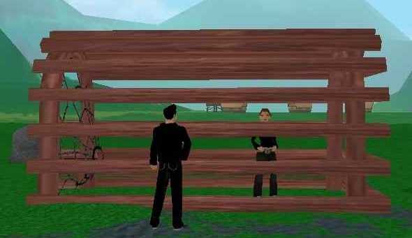
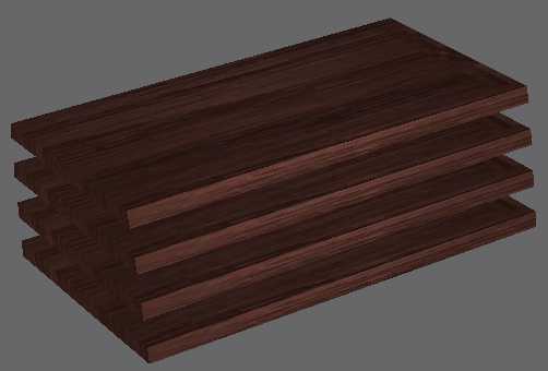
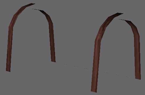
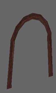
[First posted Feb 18, 2004. Last updated Feb 18, 2004] This tutorial explains how the Lobster Trap was modeled within the limiting constraints of There polygon budget, yet seemingly contained more polygons than allowed, due to the use of illusion modeling. You should have read the Shark Builder Tutorial first. This tutorial assumes that you are familiar with gmax and There modeling. It is not an entry-level tutorial. First, let's describe the problem we are trying to solve. We want to create a lobster trap structure which looks like the following picture. As with every thumbnail picture in this tutorial, you can click on it to see the actual enlarged picture.
The Shop builder template has the following constraints:
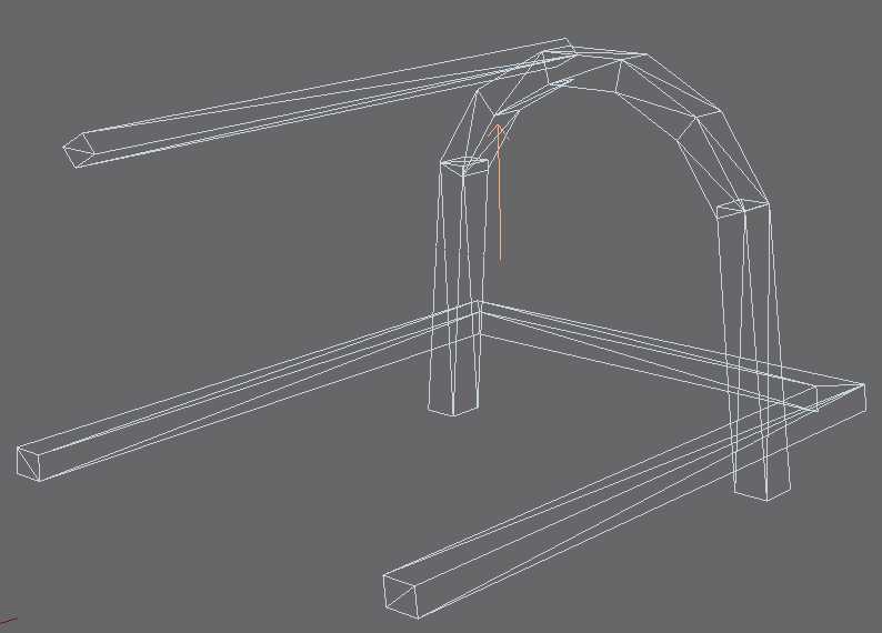
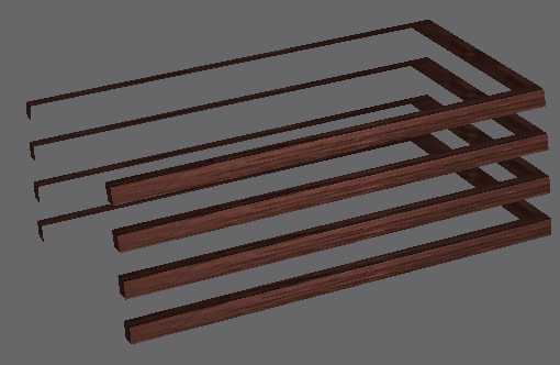
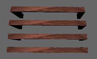
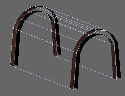
For the purpose of this tutorial, I use gmax's definition of faces and polygons. A face is a triangular mesh containing three vertices. A polygon is a collection of coplanar faces. There documentation generally refers to triangles as polygons. So, usually you see 'Max Polygon Count' instead of 'Max Face Count'. Just mentally replace Polygon with Face. While 200 faces for LOD0 seems like a large quantity, it isn't. Let's do a simple back-of-the-envelop calculation to verify my claim. The trap is composed of 4 kinds of parts. There are 2 arches, 5 U-shaped frames, 4 beams and 1 net. In the illustration below, you will find an arch, a frame and a beam.
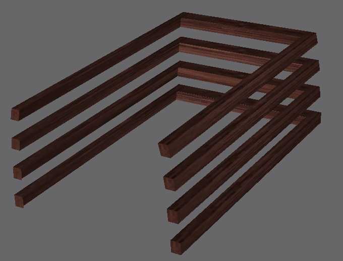
Now, count the number of faces in each part. The arch contains 60 faces. The frame contains 28 faces. The beam contains 12 faces. Ignoring the net, to assemble a trap, we need 120 faces for arches, 140 faces frames and 48 faces for beams. That is a total of 308 faces, not to mention that we need a few more for the net. Clearly, we can't model the trap this way under the maximum number of 200 faces for LOD0. So, what can we do to create such a trap without sacrificing structural complexity? The answer is what I call 'illusion modeling'. Let's start with 4 frames. Instead of modeling the frames as "solids", we can create an apparent illusion of frames by inventing multiple virtual polygons from a single polygon with the help of opacity map, and by assembling these virtual polygons into solid objects.
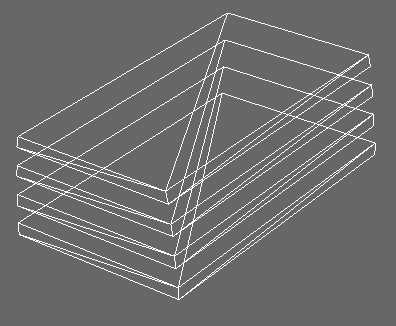
We start with 4 flattened cubes.
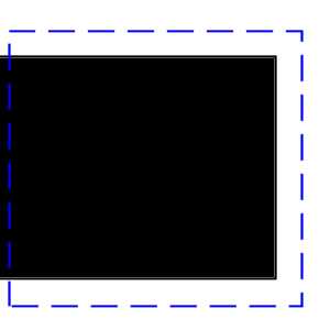
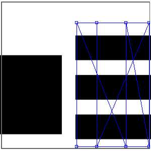
Select the indicated polygon and edit its UV map such that its UV vertices appear outside of the black center of the opacity map. Recall that a white pixel in an opacity map represents opaque surface, while a black pixel represents transparent surface. Perform the same operation for all upward and downward-facing polygons.
We have just chiseled out the middle of these polygons to create an almost credible illusion of U-shaped frames. Of course, you need to do the same opacity exercise to the opening side of the flattened cube, in order to create the side opening illustrated below.
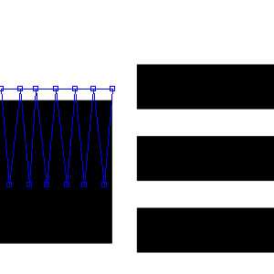
We will now cover the inner faces of the frame with more virtual polygons. To to this, create a big cube and turn all normals inside out. Remove upward and downward-facing polygons to open up the cube. Also remove the polygon on the net side. Because the normals are inverted, in the illustration below, you only see two sides out of the three inner sides.
Use UV Unwrap editor to edit the UV map of these 3 polygons to resemble the map shown below. As a result, we now effectively cut up each polygon to form 4 virtual polygons. Together with earlier virtual polygons, we have now created an illusion of solid frames.
Recall that regular method of creating solid frames required 28 x 4 = 112 faces for the 4 frames. We have achieved the same result with a total of 54 faces. "Gee, I am going to model every future project using this wonderful illusion modeling", you say. Before you do such foolish thing, remember that there is no such thing as a free lunch. For a start, I spent a lot of time thinking about the best way to model these virtual polygons. Some inquiring minds would probably ask, at this point, "why didn't you model the outer surfaces the same you modeled the inner surfaces?" After all, I would have saved even more faces doing it that way. The answer would be apparent when you look at the frames from the side as illustrated below. Basically, I needed a curved outer surface to match the arch that I would model later.
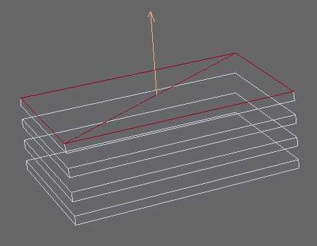
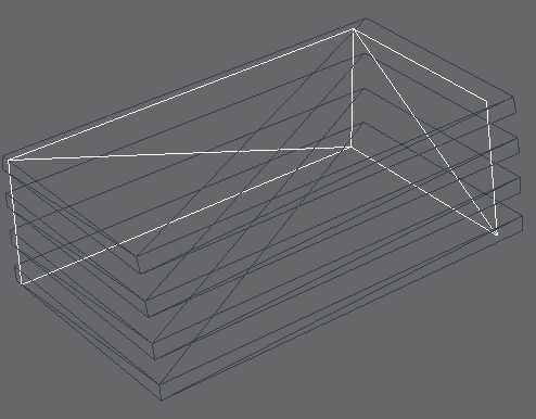
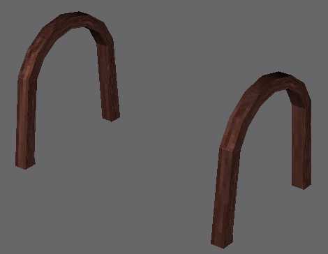
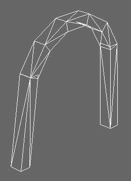
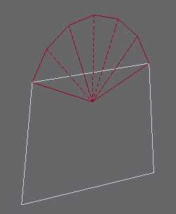
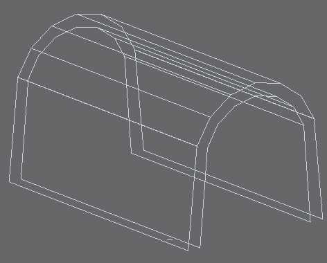
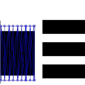
Secondly, I spent a lot of time perfecting the UV map and the opacity map, so that virtual polygons match without creating obvious seams. And lastly, you are really trading texture quality for structural complexity. Had I not used illusion modeling, I could have immediately doubled the resolution of my texture map, as I would not need an opacity map. Also, without illusion modeling, I could tile my texture map to cover more area with the same pixel count.. Now, how do we apply the same principle to the two arches? If you are the kind of person that likes to figure out thing by yourself, then perhaps you want to stop reading the tutorial at this point, and take this challenge as a exercise. If you need a bit of hint, look at the wireframe mesh of regular arch shown below. Then compare that to the mesh of illusion-modeled arches.
Let's tackle the problem in two steps. We'll create virtual polygons to cover the side surfaces first. Then we will create more virtual polygons to cover the front and back surfaces.
First create faces as indicated below.
Then map these faces in UVW Unwrap editor, so that only small portion of the surface is painted.
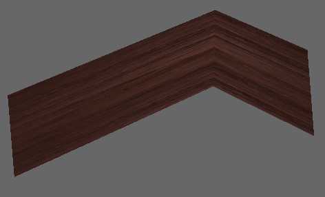
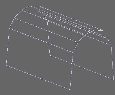
Now create faces to cover both outer and inner surfaces of the saddle. Following images shows the saddle rendered with two-sided texture.
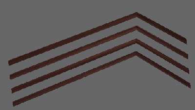
Same faces with single-sided texture.
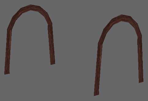
Edit UV map to saddle the UV vertices on the two sides of the transparent (black) region. When we assemble the saddle with the side polygons created in the last step, we have a total of 64 faces for the two arches. Compare this with the 120 faces that would have plagued a non-illusion-modeling artist, and you should feel pretty happy.
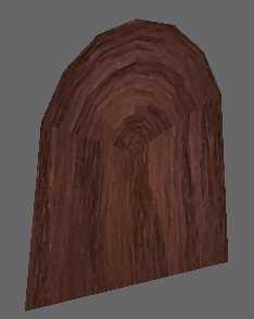
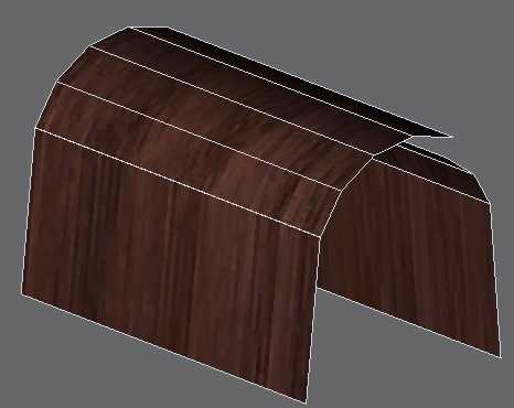
Well, we are done with the trap. Let's look at the final mesh and rendered picture for a last time. I haven't tackled the 4 beams on the top, the top-most frame and the net. But these do not lend themselves to great savings via illusion modeling. However, we have used only 54 + 64 = 114 faces so far... we still have 86 faces to spend on the remaining parts.
If you are interested in seeing more illusion modeling objects, visit this page... | |||||||||||||||||||||||||||||||||||||||||||||||