![]() Reduce Polygons
Reduce Polygons
![]()
![]()
![]()
![]()
![]()
![]()
![]()
![]()
![]()
|
|
|
It is time to go back to gmax and finish the model by reducing vertex and polygon counts. Recall that the constraints for the 3 LODs are:
This is how were are doing so far:
We need to remove at least 26 vertices and 138 polygons for LOD1. Clearly, polygon count is going to trouble us.
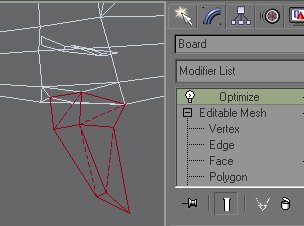
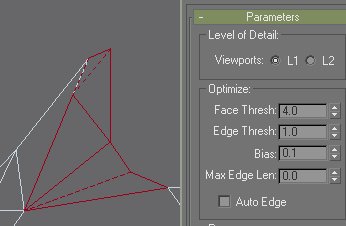
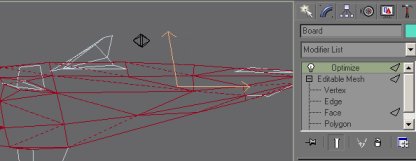
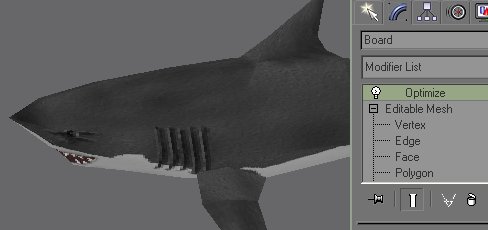
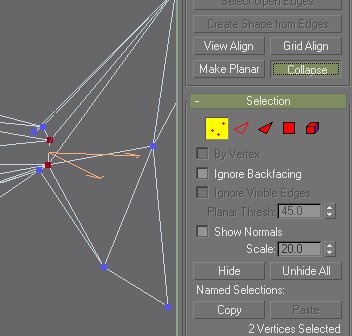
We start by hiding everything, including all helper objects, except the LOD1 board. Use Face SubObject selection to select a pectoral fin. Then add a Mesh Optimize modifier to the modifier stack. Optimize will only work on the selected faces. This allows us to optimize just the selected parts of the fish. The default value should remove quite a few polygons from the fin. After you are satisfied with adjusting the optimization parameters, right click on the optimize modifier and collapse it onto mesh. Always remember to collapse before you take on another task. Repeat this procedure on the other pectoral fin.
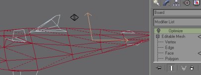
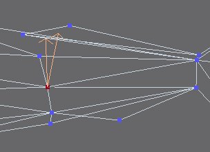
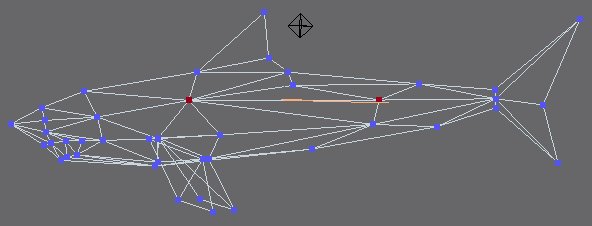
Apply the optimize modifier to each part of the dorsal fin. Remember to collapse modifiers before you work another area. Collapse the edge indicated above manually on both sides. The collapsed edge is replaced by a vertex. You need to move this vertex up a little to make it look nice. If you perform optimization on two sides separately, you may end up having two vertices that occupy the same 3D location. Use Vertex Weld to merge them to reduce vertex count.
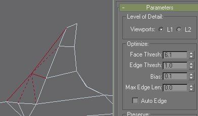
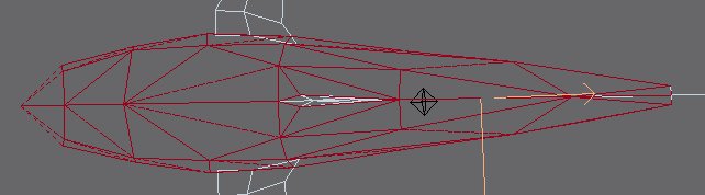
If we simply apply Optimize to the whole shark, it may produce undesirable effects. For instance, the second dorsal fin and the anal fin will be removed by optimization settings tuned for the main body. The caudal fin will also be badly damaged. We need to select just the main body for the next optimization. Choose Face subobject selection. Click on the Select Object button. Drag a bounding box to select most of the main body. Use shift-drag to remove a set of faces by bounding box. Use control-drag to add more faces by bounding box. Use control-click to toggle individual faces. Remember to exclude the second dorsal fin and the anal fin in both sides of the body from the final selection.
Add a Mesh Optimize modifier. You can see the effect of the optimization by toggling the light bulb icon beside Optimize modifier on and off.
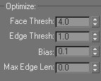
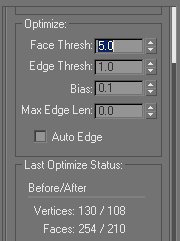
You an preview the effect of optimization on the surface of the shark by switching the viewport to smooth rendering. Notice that the texture may look weird, due to removal of polygons from the texture map. You will suddenly see that the border between some polygons now look very conspicuous. Don't worry about this. At the end, we'll create another UV map for LOD1 to fix this problem. You can experiment with the optimization settings and see how it reduces vertices and polygons at the bottom of the modifier rollout. Make sure that optimization does not damage important areas such as the jaw and the area where your avatar stands. Also make sure that the two lateral lines running from the tip of the head to the tail are not altered or interrupted by optimization. These lines will allows us to align the UV map later, if we choose to re-create UV map from ground up.
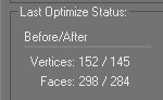
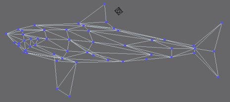
With a face threshold of 6, we are left with 105 vertices and 204 polygons. You can now collapse the optimization modifier. If you are worried about over-optimization, you can use Edit | Hold to save your current state. I usually make a copy of the gmax file in regular interval, especially before major irrevocable changes such as collapsing modifiers. We have to eliminate 44 more polygons. Boy, this is going to be hard.
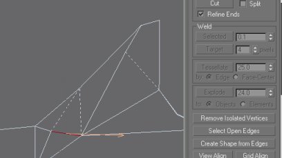
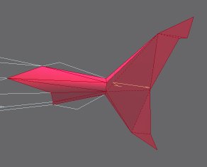
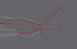
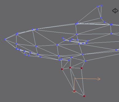
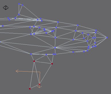
Select the caudal fin and a few adjacent body polygons. Mesh Optimize does a really poor job on this one, no matter what settings you use. Remove the optimize modifiers. We have some manual job here. Switch to vertex subobject selection, so that all edges are visible.
Use Weld Target to collapse two vertices onto a third vertex at the tip of the caudal fin. This operation eliminated 4 polygons. Weld another vertex to the lower tip of the fin to save two additional polygons.
Use Collapse to merge two vertices into one. This is different from Weld Target in that gmax places the merged vertex in the middle of the two original vertices. We are now down to 194 polygons. Weld a few more vertices in the tail region. We are now down to 98 vertices and 190 polygons. Then we sabotage the beautiful dorsal fin to trim polygon count down to 180.
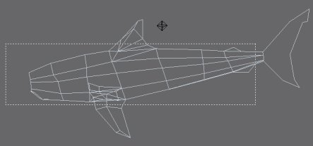
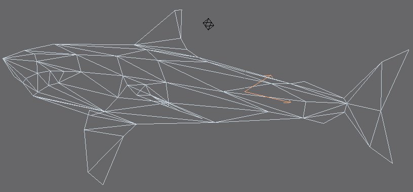
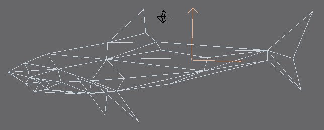
Weld a few more vertices in the pectoral fins and we are now down to 172 polygons. Just 12 more polygons to sacrifice. Notice that previous optimization on the body produced bad triangulation near the jaw. After fixing these triangles using edge turning, we notice that some polygons/vertices can be removed. We are down to 168 polygons. Make sure that you did not mess up the texture of teeth, which took me a long to time paint. Do not remove any vertex around of the border of mouth. This allows us to preserve the texture of the mouth. After more damages to the jaw and to pectoral fin again, we finally got down to 83 vertices and 160 polygons!
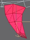
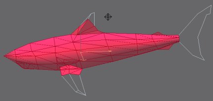
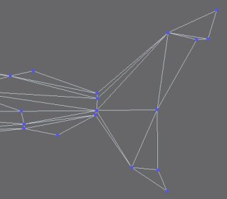
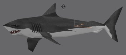
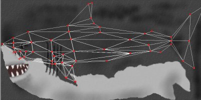
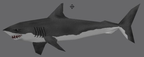
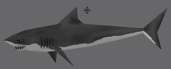
Final LOD1 mesh is shown above. We have messed up the UV map by collapsing/welding vertices. The texture looks terrible on the shark now. This caused by disappearance of vertices and polygons. We can see this effect clearly, if we add an Unwrap UVW Map modifier temporarily and look at the UVW editor screen.
Use the same technique in the Create Texture Map chapter to create a UVW Map for LOD1. Do all the rotations prescribed earlier. We also need to rotate the UVW Map gizmo by -0.05 around z axis. Again, rotate all UV vertices in the editor to match bitmap orientation. Then we need to adjust all vertices to fit the shark to the bitmap... but I guess this is too much trouble. Perhaps we are better off fixing the wrecked UV map...
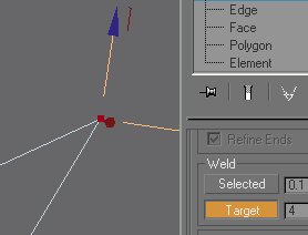
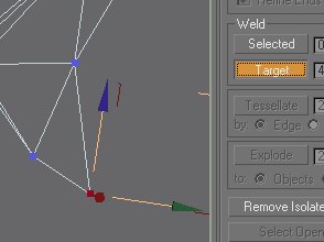
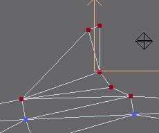
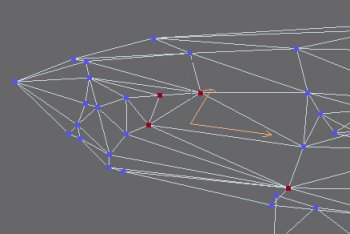
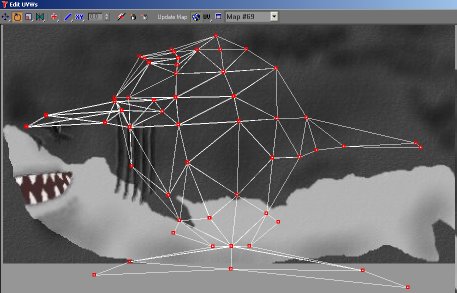
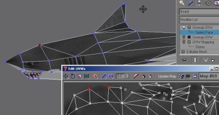
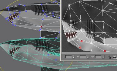
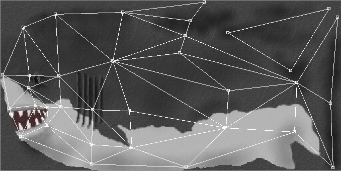
Let's experiment with this idea. Toggle off the UVW Map and the UVW Unwrap modifiers for now. Add another UVW Map Unwrap modifier to see the wrecked map. Notice that there are many isolated vertices in the UV map, because their original polygons have been optimized away. Don't worry about removing these vertices at this time. Leave them, because we need them as location markers. Also notice that some individual UVW vertices now appear as one single viewport vertex, because of our collapse/weld operations during optimization. We need to weld these UVW vertices. You can highlight multiple UV vertices and check whether they appear as a single vertex in the viewport. Make sure you use Target Weld or normal Weld operations correctly, depending on the situation. For the two UV vertices illustrated above, use Target Weld to preserve the location of the target vertex. After the operation, the viewport should show no sharp boundaries between adjacent polygons.
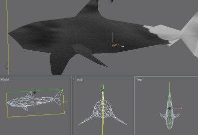
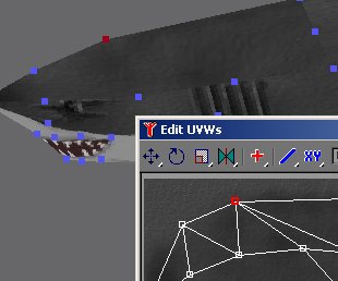
Some viewport vertices may have been moved during optimization. For these we can't simply use Target Weld; we may need to move UV vertices. But how do we know if a viewport vertex has been moved? Fortunately, we have saved a shift-cloned copy of the LOD0, so we can unhide the 'Shark LOD0 Uncollapsed' object we saved previously, and show both LOD0 shark and LOD1 shark in the viewport for comparison. It proved to be much easier to adjust the broken map than to recreate one from the ground up. For each viewport vertex we Target-Weld, we need to target-weld the corresponding UV vertex. We don't need to worry about adjusting UV vertices to the right location in the map. Finally, select all vertices and do a final 'Weld' operation to merge vertices we may have missed earlier. You'll be surprised how many vertices you can save by this simple operation. This will also remove isolated/overlapping UV vertices that may have been obscured by other UV vertices during translation.
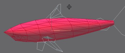
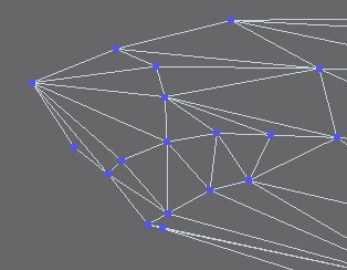
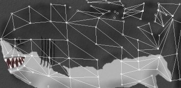
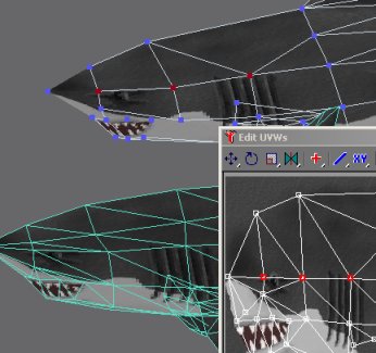
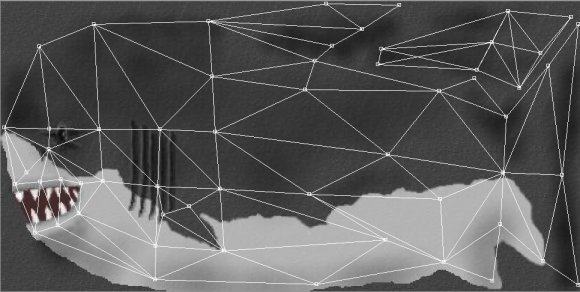
Here we have the final UV map for LOD1, the texture mapped shark and the polygon frame. You can now delete the two modifiers we toggled off earlier. Also collapse the UVW Map Unwrap modifier. Feel free to make a copy of the LOD1 for later reference. Remember to hide the clone
Export this scene to There model format again. If you have not unhidden the other levels of details, then you will only see LOD1 in the previewer. This is fine. The previewer shows that we have only 125 vertices, way below the constraint. Number of polygons remain unchanged by the UV map editing.
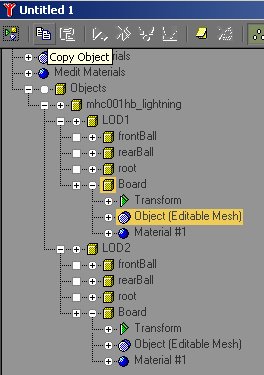
We can now copy the LOD1 Board and past it onto the LOD2 Board in the Track Viewer. Remember to paste a 'copy', not an 'instance'. Now we need to eliminate 68 polygons to satisfy the LOD2 constraint. We'll start with the obvious places: fins. Eliminate the second dorsal fin and the anal fin. At this level of detail, we don't care about such small polygons, in the grand scheme of things. Answer yes, when asked whether to remove isolated vertices. Greatly simply all other fins. Represent them with single triangles. Try to collapse polygons whose vertices do not appear on the outline of the shark body in side and top views. We are down to 59 viewport vertices and 114 polygons. We cannot weld vertex that lie on the v-z plane to to other vertices, because such operations will result in polygons that cross the v-z plane. This kind of polygons cannot be easily planar-mapped from the side, because you need to produce a symmetrical UV texture for it. We simplified the mouth and removed even more polygons from the fins. Finally, we have 48 viewport vertices and 92 polygons.
We have just finished all there levels of details!
We can now perform some final examinations and submit the model for approval.
|